

BIFORIUM / PROFILE GUIDE
HOW TO READ A PROFILE SECTION
A section is more than the shape of aluminium or PVC. It reveals the construction logic: frame and vent, glazing position, thermal break, gaskets and drainage.
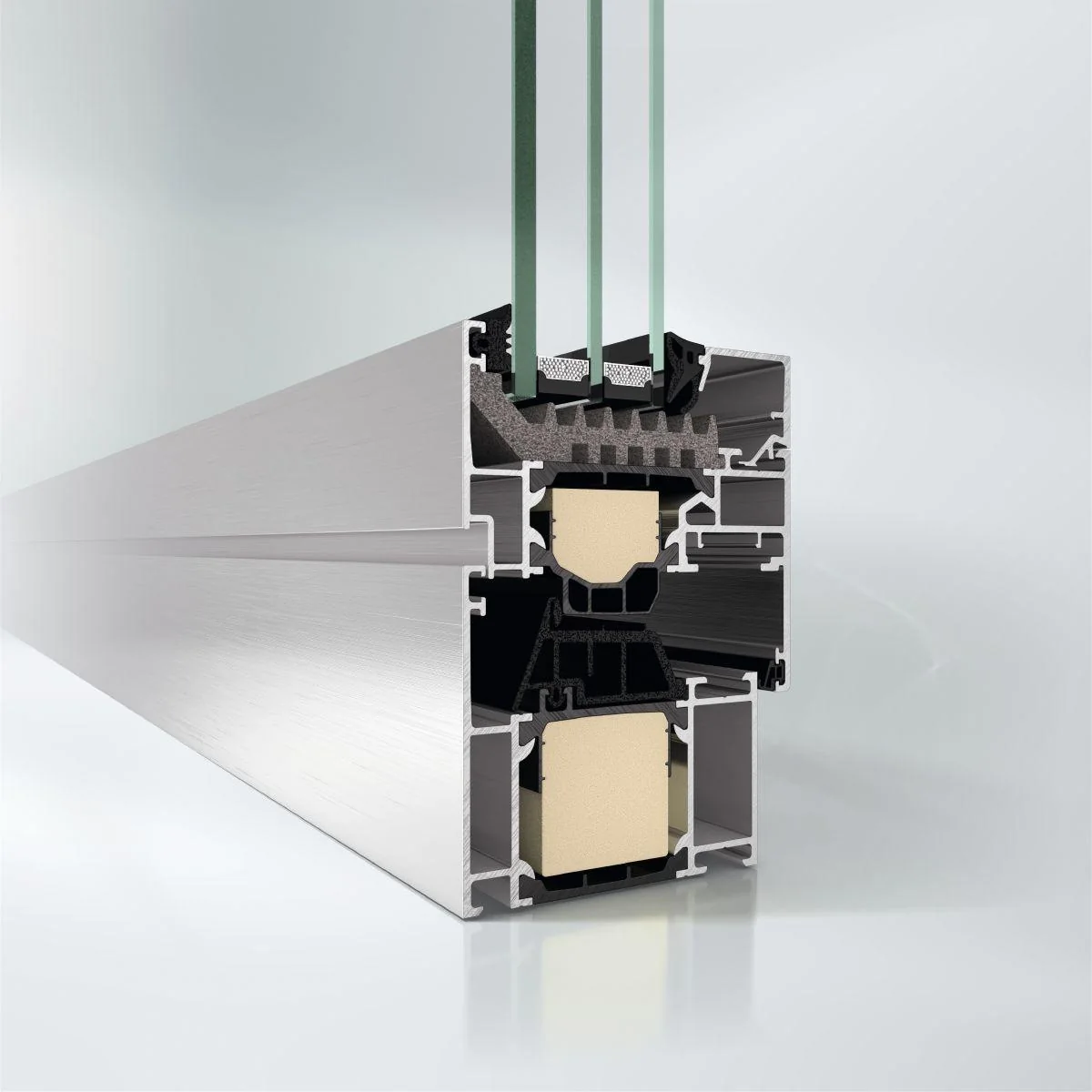
Reading the section correctly lets us compare real system geometry instead of logos. It still does not replace the drawing of the actual element, engineering checks or the installation junction.
Find the frame, vent and glass first
The frame is fixed to the opening, the vent moves relative to it, and the insulating glass is retained by a glazing bead or another system-specific arrangement. Fixed and opening elements use different profile combinations, so two sections from one platform can have different visible widths.
Do not confuse system depth with sightline
System depth is measured across the profile, from the internal to the external plane. The visible sightline is read in the façade plane. It forms the frame, meeting-stile or mullion line that remains visible after installation.
A thermal break is not the complete Uw
In aluminium systems, polyamide strips separate the internal and external profile shells; in PVC, chambers, material and reinforcement form the thermal strategy. A section helps explain frame construction and Uf, but complete-window Uw also depends on glass Ug and area, edge effects and actual window geometry.
Inspect the glazing zone
The section shows glass seating, rebate height, glazing bead, gaskets and the available infill-thickness range. A thicker IGU is not automatically better: build-up, mass, edge, safety and hardware compatibility must be checked together.
Gaskets and drainage form working layers
Gasket lines create consecutive air- and water-control zones. Drainage cavities lead water back outside. One catalogue section does not always show the whole route, so low thresholds, façades and interfaces need additional manufacturer details.
Hardware creates hidden constraints
Grooves, chambers and wall thickness determine which hardware and reinforcement can be fitted. Permitted vent size and mass come from the tables for the exact configuration, opening type and hardware set — not from the section image alone.
A system section is not an installation junction
The system section does not include the full wall build-up, insulation, structural support, anchors, membranes, façade interface or finished levels. A working junction connects the profile to the building and explains load transfer, water management and continuity of insulation.